
Jim Shaw and the Rover P4
'Mr. P4' (Vehicle Project Engineer 1958 - 1964)
Beginnings
When my father joined the Rover Co. in July 1950 the Land-Rover had already been in production for over eighteen months and the P4 car for nine months. Perhaps it was seeing these 'modern' vehicles, so different from the 1930s styles retained by necessity thoughout the war years, that attracted him to join Rover?
The Experimental Department of those days had wide-ranging responsibilities, carrying out development work on new projects, current vehicles and production support. My father must have been involved in all of these activities, with a bias towards Land-Rover support.
Gearboxes and Overdrive control
The earliest papers that I hold go back to 1952 and they are car-related but it isn't clear if the development work was speculative or intended for incorporation in P4. In January 1952 my father was suggesting improvements for the control of what was called the WRB Gearbox. A second arrangement called the De Normanville gearbox was also being developed. The WRB gearbox provides three forward gears, 1, 2 and D, while the De Normanville had four, 1, 2L, 3L and D. Both gearboxes appear to be have been semi-automatic and used solenoids to operate hydraulic valves. Presumably both gearboxes were to be have been coupled to torque converters. ('WRB' was an abbreviation for (William) Robert Boyle, Chief Engineer. During his career he had at least 12 patents to his name but otherwise seems to have been largely forgotten in motoring history).
My father's early involvement in electrical matters is perhaps not surprising. He had been interested in building radio receivers since a young boy and had studied electrical engineering to HND level, something not necessarily the case for his fellow vehicle engineers with a purely mechanical engineering background. At that time the electrical systems of cars were relatively simple and their development was in the hands of specialist suppliers like Joseph Lucas Limited. Rover's electrical section barely existing.
In April 1952 Lucas offered a set of control circuits for the de Normanville overdrive following on work for the Ford Motor Co. in which they had edeavoured to reproduce the driving characteristics of the Borg Warner overdrive. (The Borg Warner overdrive was operated directly by a solenoid and if selected engaged at a set road speed if the driver momentarily lifted their foot from the accelerator pedal. Because it incorporated an 'over-run' clutch, engine braking wasn't available. Although a 'kick down' release was available, the ignition was momentarily cut in order to take the load off the locking pawl and to allow it to disengage. It ceased to be manufactured in the early 1960s). Lucas realised that the benefits of the de Normanville overdrive, full-power changing and engine braking, were being lost and alternative control schemes were needed.
The first model in the P4 range, the Rover 75, followed the American fashion of the time of using a steering column-mounted gearchange, (designed by Frank Shaw, no relation). This proved to be unpopular with customers and so a floor-mounted control was developed with a long, cranked operating lever. This was supposed to allow the continued use of a front bench seat, another American fashion, albeit on a rather narrower car! Clearly my father must have had some involvement in its development as he was filmed carrying out 'life testing' on a workshop example. (I have speculated that his 'assistant', in the white coat was actually Robert Boyle).
In January 1954 an electrically operated clutch by Smith's Industries was being considered, which would have done away with the clutch pedal . Possibly related to that my father prepared a draft patent application for what was called a 'Tip-Cat' switch.
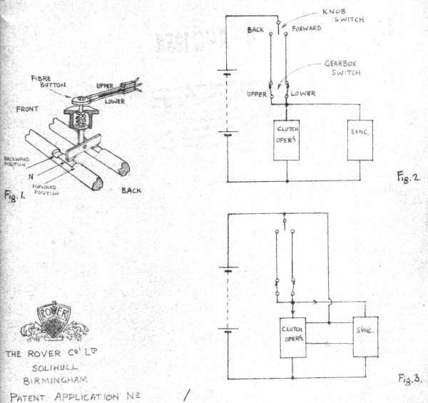
The object of the present invention is to provide an interlock such that the foregoing device is:-
- (a) inoperative if hand pressure is maintained after completion of a gear changing operation.
- (b) inoperative if hand pressure is applied in the direction of the last completed gear changing operation.
- (c) operative on application of hand pressure in the direction opposite to that of the last completed gear changing operation.
- (d) operative in either direction from neutral at all times.
There is no indication of who the inventor was.
In November 1955 Joseph Lucas Ltd. offered five control schemes for overdrive operation, namely:
- E&D 738 - Manual Control Circuit
- E&D 739 - Semi-Automatic Control Circuit
- E&D 741 - Borg Warner Circuit
- E&D 744 - Manual control gear change sequencing
- E&D 602 - Basic Standard circuit
The same month Smith's Industries were asked to provide speed-operated switches and Bowden cables for overdrive control, (Borg Warner-like). The following January the requirement changed to a vehicle fitted with a torque converter and Laycock (de Normanville) overdrive. Subsequent correspondance suggested that Rover had doubts that the switches ('governors') could be set within the required limits and that there were problems with vibration. Smith's were confident that they could meet the new requirement.
The final production arrangement for manual gearbox cars was settled by October 1955 and my father produced this guide:
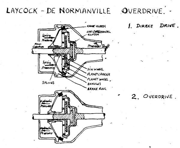
Brief description of operation of De-Normanville Overdrive on P.4. '90' 1956 models.
Overdrive unit.
Normal production type De-Normanville unit operating as follows.
1. Direct drive.
Engine drive torque in direct drive is taken through a roller type freewheel.
Engine overun torque in direct drive is taken through a cone clutch in parallel with the free wheel.
Engine & reverse gear torque in reverse is taken through the cone clutch in parallel with the free wheel.
The cone clutch is applied by spring load.
2. Overdrive.
An overdrive gear of 1.28:1 is given by an epycyclic train brought into operation by hydraulic engagement of a second cone clutch and disengagement of the above direct drive cone clutch. The output shaft is allowed to go faster than the input shaft by the freewheel unless the car is allowed to go backwards in overdrive when the gear will lock up.
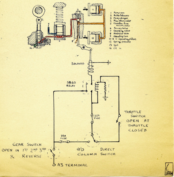
Control of engagment.
Overdrive is engaged by hydraulic pressure supplied by an oil pump on the input shaft through a valve operated by exciting a solenoid on the right hand side of the overdrive unit.
Direct drive is obtained by opening the above valve to the gearbox sump by switching off the solenoid.
Control circuit.
The solenoid can only be excited when the car is in top gear, due to an isolating switch on the casing connecting the main gearbox to the overdrive unit.
Further the column switch below the steering wheel on the left has to be down.
Direct drive is obtained immediately when leaving top gear in the main gearbox or when switching the steering column switch up with the throttle part or full open.
An over-riding circuit prevents changing down to direct when the throttle is closed to prevent momentary locking of the rear wheels and snatch in the transmission. Additionally the circuit is fused in such a way that blowing a fuse does not result in an undesired change into direct drive.
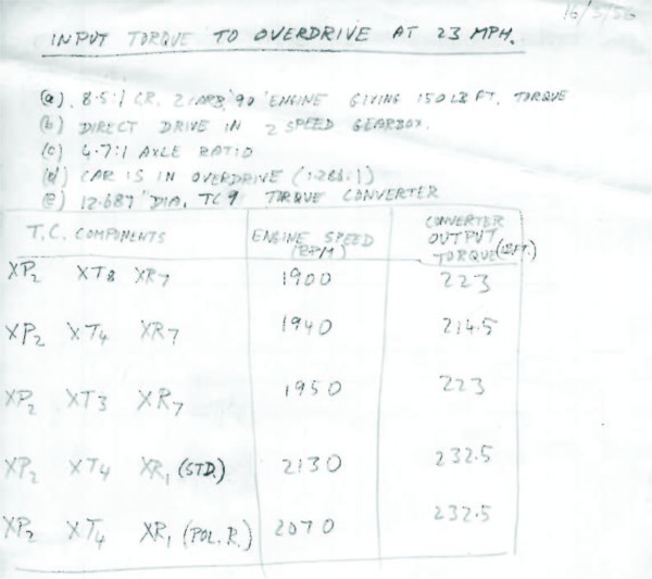
In March 1956 my father produced a report on Rover 90, SNX 39, fitted with a TC 8 torque converter, 4.7:1 axle and 0.778:1 overdrive giving the manifold depressions relating to various throttle openings and road speeds. This suggests that a pressure switch was being considered for overdrive control. Auto Transmissions Ltd., (manufacturer of the de Normanville overdrive), were advised that Rover was aware of the 210 ft.-lb. (163 Nm) limit for the present unit and that it had been allowed for in the current design, however the proposed P4 with a Laycock de Normanville overdrive and torque converter would increase the moment of inertia of the engine. Auto Transmissions were invited to test the prototype car that had been produced, (SNX 39?). W.R. Boyle was advised in May 1956 that the TC 9 torque converter was to be used in production and supplied with test results obtained from a TC 6 torque converter. (The torque converter appears to be composed of three major components that were made in more than one form so that several possible combinations were possible).
Clearly the simple overdrive scheme had performance limitations and in April 1956 new overdrive control ciruits were proposed for the '60', '75' and '90' models giving a 'kick up/kick down' feature for the manual gearbox and torque converter cars. The throttle switch in the simple scheme was now to have two contact sets, one open up to eighth throttle and the other open up to half throttle. The torque converter cars would also include a speed-sensing 'governor' switch.
Engines
Despite obtaining a distinction for Heat Engines following his OND studies and his experience on a variety of aircraft engines, including jet engines, during his RAF service my father was never directly involved in engine development during his time at Rover.
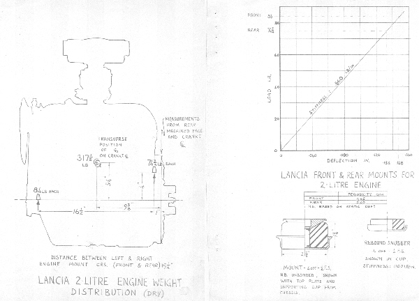
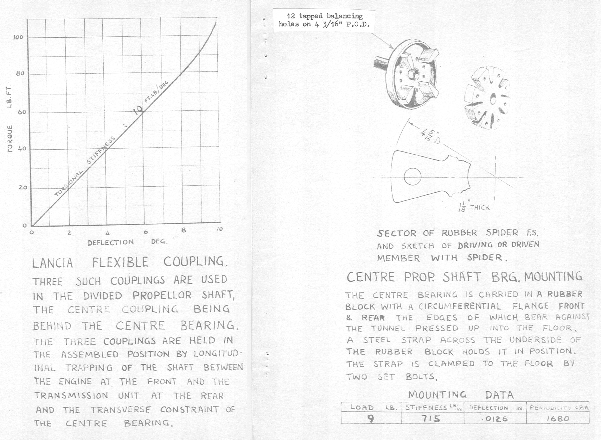
In 1950 Lancia of Italy produced the Aurelia, the first production car to have a V-6 engine. In terms of styling the Aurelia had a lot in common with the Rover P4. Rover had also been working on-and-off on its own V-6 engine since the mid 1930s so this car must have raised some interest, perhaps even to the extent of purchasing an example? My father produced a report in January 1953 giving the weight distribution of the Lancia's two-litre engine, the stiffness of the its mounts and a description of the flexible couplings. Surely this was only possible after a strip-down?
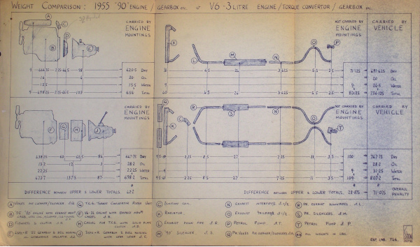
Rover's own V-6 was the subject of a study by my father in October 1955, comparing the three-litre engine with TC6 torque converter and three-speed manual gearbox against the 1955 Rover 90 engine and four-speed gearbox. Taking into account all the engine auxilliaries, radiator, silencer, fuel pump and fluids the V-6 was expected to add 71.1 lb [32.3 kg] to the vehicle weight.
Sometime in the late 1950s Rover definitely experimented with a diesel engine in the P4. My recollection, as a small lad, was that there was a Rover 80 so fitted. That made sense in that the '80' engine was derived from a Land-Rover diesel. Some present-day authors suggest a diesel was proposed for the Rover 90 to sell as a taxi to Brazil. (I remember some tins of sardines being brought home that bore the Rover badge around that time. This would have been samples for a possible barter arrangement. A foreign buyer, not having sufficient pounds sterling, would effectively buy tinned fish locally that would be shipped to a UK grocer who would pay Rover in pounds sterling. If this four-party deal couldn't be agreed then the sale of Rover vehicles wouldn't have gone ahead).
My father had development responsibilities in 1960 for introducing the new engines for the '80' and '100' models and later, in 1962 introducing the '95' and '110', the later with the Weslake cyclinder head.
Bodywork
As Vehicle Project Engineer of P4 from 1958 to 1964 my father guided the development project for the 1959 facelift.
Since the P4 range had been launched in 1949 the opening panels of the car, the bonnet, boot lid and doors, had been made of aluminium alloy, originally because steel had been in short-supply post-war. Aluminium alloy panels lack the elasticity of steel and are far more ductile. As a result if a customer closed the doors other than by the handle, using a palm or a back-side the doors were liable to dent and not spring back into shape.
In the final years of P4 my father and his assistant, Ken Robbins, undertook trials to see if these panels could be stiffened in any way. Glass fibre matting and increasing the metal gauge were tried but that pushed the costs up and in the end using steel seemed to be the only solution to this perennial problem. (I remember a P4 running about with bags of lead shot on the floor to bring the vehicle weight up that of an all-steel car.)
Around the same time there was a trial of plastic door handles, supposedly because customers found the metal ones too cold in the winter. They were the same shape as the metal ones and were finished in chrome but the operating button was left as plain red plastic. (The plating would have quickly worn off if it had been applied to the buttons).
The side lamp tell-tales, small chromium-plated 'horns', introduced at the end of 1956, were a development of my father's. (He had to experiment with Plasticine and ball-bearings to establish the correct position). Robert Boyle, by then a director, had them fitted to his car when they were first produced. Shortly afterwards he complained that they weren't working - it turned out that they were, it was his side lights that weren't! In any event they were eventually discontinued, probably because legislatures were becoming concerned about protusions, like mascots, on the front of cars.
Brakes
Citroën launched the DS19 at the Paris Motor Show in October 1955. The car's unusual shape and novel suspension system attracted a lot of attention both amongst the public and other car manufacturers. In the late 1950s Rover bought at least one, (it was yellow and the internal trim standards were very poor!). It has been suggested that its body shape influenced that of the Rover P6. What it certainly did as far as my father was concerned was convince him that 'full power hydraulic brakes' was what Rover should go for.
Ever since the hydraulic brake had first been used on motor vehicles legislatures around the world have been wary of it! A mechanical system has 'nothing to go wrong', sturdy rods and links that can be seen to be in place, whereas the hydraulic system has hidden fluid that may leak past one of many seals and may not be there when required. That is why UK law requires a secondary braking system, the handbrake or parking brake. The 'full power hydraulic brake' maintains a proveable reservoir of fluid at high pressure and even if there is a leak it should be capable of bringing the vehicle safely to a stop.
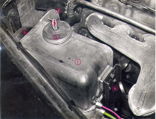
Towards the end of 1959 a Full Power Hydraulic Brake system was fitted to Engineering Department '105R' VWD 130. (Girling fitted a similar system their Rover test car VUE 814). The Rover installation was described as:
The Test Vehicle
This model was chosen because it was convenient to arrange a belt drive from the front end of the crankshaft and provide the space necessary to mount the "pump/unloader valve/accumulator/reservoir" unit. The mounting position was such as to allow a gravity return from the control valve mounted on the pendant bracket fitted to this model.
The vehicle was fitted with the 1960 P.4 rear axle assembly, the "standby" scheme for 1960 P.4 front disc brake equipment (using a smaller caliper than that now standard compared to 1960 P.4 & disc braked P.5) fitted by adapters to the pre-1960 stub axle/steering lever assembly and 1960 P.4 wheels (P.5). Line pressure and Accumulator pressure gauges were fitted in the N.S. glove locker. A Lucas dual warning light system was fitted to indicate (a) safe/unsafe state of accumulator pressure (b) working/non working of the warning light system.
The system wasn't without its problems, various leaks causing pressure reduction on a parked car over a period of several hours to several days, and operating noises described as being like 'water hammer'. Nevertheless the system was still capable of 38 full brake applications after the low-pressure limit had been reached. Such problems are typical of new systems and would have been expected to be resolved in time. A report in December 1959 concluded:
An improvement in the shape of the Deceleration/Pedal Effort characteristic is necessary to reduce the sensitivity up to about 8 ft/sec2 [2.4 m/s2]. As it stands the feel is however a considerable improvement on the Citroën DS19.
The cost of the system might be reduced by the use of a gear pump instead of the swashplate plunger pump.
The economic chances of the production use of the system would be greatly enhanced by the parallel use of the pump to supply a power steering system and cost saving per vehicle might result if additional centrally supplied hydraulic systems were used.
J.Shaw
[signed]
My father had been responsible for the introduction of front disc brakes with the '80' and '110' models in 1960, ending eleven years of front drum brakes. It was unlikely that the full power hydraulic brake was seriously expected to be fitted to a production P4, it would have required brake manufacturers like Girling to be convinced that there was a bigger market than P4. Nevertheless development continued at a low level.
By 1963 it was apparent that brake systems were becoming more complex, partly because of changes in international legislation and partly as a result of electronic technology making anti-lock braking systems an economic option for cars. As a result my father took on the new role of Brake Project Engineer, relinquishing responsibility for P4 the next year as his work on braking systems increased.
In April 1964, in company with Spen King, Dick Oxley and Gordon Bashford he met with a Girling team to discuss future options for the full power hydraulic brake. It had been thought that future models of P6 might need such a system. Spen King was reported as saying:
"some form of levelling would be a requirement for all new vehicles to cater for the considerable variation between laden and unladen weight without the necessity to resort to increased suspension travel or stiffer springs. High pressure oil was considered to be the right mediuum for levelling control and this suggested the possibility of operating the brakes from the same source to eliminate the vacuum servo."
And so the stage was set for P8, but that is another story!
P4 anticipated the modern ideas of a choice of engine sizes, diesel engines and plastic door handles plus some that never 'took off', gas turbines and full power hydraulic brakes. Not bad for a staid 'Aunty'!