
The Laight-Shaw Compression Test Machine
A machine used by the Rover Co. Ltd. for 20 years
When my father joined the Rover Company Ltd. in July 1950 as a Technical Assistant in the Experimental Department he worked on various engineering problems as they cropped up across the whole of the Rover product range. This would have included special rigs and the like, needed by the department and for product testing. There is some evidence that he devised a controller to sequence the starting, running and stopping of a bank of engines in a test cell and carried out some work on a gas turbine engine balancing machine.
There clearly was a need for some sort of test machine to apply compressive forces and that task fell to my father and his colleague Charles 'Harry' Laight. Roughly speaking I expect that Harry Laight was responsible for the mechanical side and my father the electrics but I have no doubt that the general concept was a co-operative effort. The machine must have proved its worth as it continued to be used for about twenty years when it became a casualty of metrication.
The earliest drawing that I have is dated 18 September 1950 but the design appears to have evolved slightly so the final machine was probably completed in 1951.
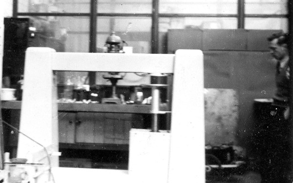
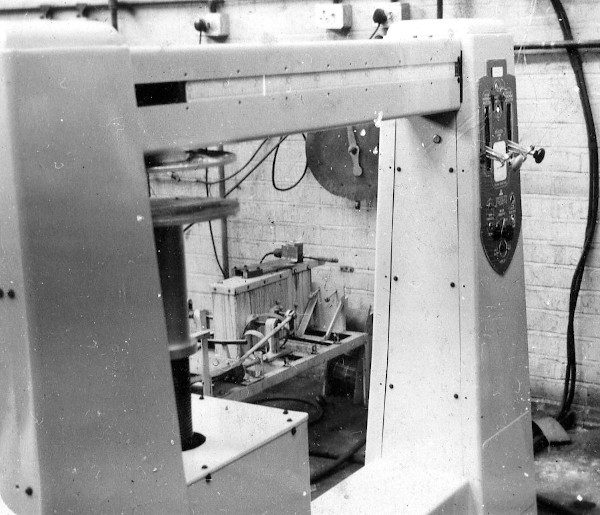
The machine consisted of a portal structure about 1.76 metres wide at the base and standing 1.3 metres high. The top of the portal frame enclosed a beam pivoted close to the left-hand side with a counterbalance weight enclosed within the left hand-frame. This weight balanced out the beam to the right of the pivot, a rider weight at its 'zero' position and a weight suspension framework enclosed in the right-hand frame.

About 100 mm to the right of the pivot was attached the upper compression plate and immediately below that the lower compression plate was mounted on a screwed pillar. In use the item under test would be placed on the lower platform and an electric motor used to drive the screwed pillar until the test piece contacted the upper plate, pushing the beam out of balance, indicated by a warning light. An inching control would then allow the pillar to be finely adjusted to bring the beam to the level position.
The rider weight mounted on the beam could be electrically driven by a wire and pulley system to apply a load of between 0 to 100 lbf (445 N) to the test piece. A scale marked on the beam indicated the position of the rider and the effective applied force.
Within the right-hand framework there were a set of four 8 lb weights and a set of four 40 lb weights. Each set of weights were suspended by wire and pulley system attached to two hand-operated levers. Each lever was fitted with a latch to hold it in one of four positions. Releasing the latch at the 'zero' position needed the operator to apply a force of 32 lbf [142 N] to hold the lever still. As the lever was moved to the next position the associated weight would land on the load application rod hanging from the beam, reducing the force on the control lever by 8 lbf.
As the load application rod was attached about 1.25 metres from the beam pivot the second-order lever action multiplied the applied force so that, depending on which control lever had been used the 'landed' weight would apply 100 lbf or 500 lbf on the test piece. Thus forces of 100, 200, 300 and 400 lbf could be applied using the left-hand lever and 500, 1000, 1500 and 2000 lbf using the right-hand lever. A door fitted to the bottom of the right-hand support allowed two extra 40 lb weights to be added to the load application rod. Thus the machine was capable of applying a force from 0 to 3500 lbf. [i.e. the left-hand lever applied increments of approx. 445 N and the right-hand lever increments of approx. 2.22 kN, giving a total of 15.6 kN]