
Jim Shaw - 'Electrician'
Early Radio to Home Computers
Introduction
For a child being brought up in 1920s Edinburgh, broadcast radio, 'wireless', was still a novelty, the BBC having only been formed in 1922 and their Edinburgh station opened just two years later. Electrical power for street lighting dated back to the turn of the century and for the tram system, 1920, but it wasn't generally available domestically. (As an aside it wasn't until the gas street lighting outside my maternal grandmother's house was replaced by electric lighting that domestic electric power became available to her in 1962).
Although there is no doubt that my father's first technical love was the motor car, now developing as something in its own right, not just a motorised horse-less carriage, the relatively new 'wireless' and domestic electricity fascinated him. While still a schoolboy he wired his parents house for power and light when mains electricity was introduced to that part of Edinburgh.
While my father undoubtedly understood the principles of radio and the associated valve (vacuum tube) electronics of the time I don't believe he ever designed a radio of his own but was quite capable of adapting published designs and creating his own control and switching schemes. One of books he kept from his childhood was 'The Boy Electrician', probably given to him when he was 13, that showed the keen lad how to make things such as induction coils, burglar alarms, microphones, telephones, Morse keys and sounders. Most projects required a minimum of woodworking and metalworking skills, however the final design for a dynamo involved making wooden patterns for the local foundry to produce castings from! This book was passed on to me and I read it avidly and absorbed its principles if not its practices which involved such things as firing up Geisler and X-ray tubes, apparently readily available at the time.
Wireless Magazines
In 1913 the magazine Wireless World was launched, followed by Popular Wireless in 1922 and Practical Wireless in 1932. During his mid-teenage years my father certainly bought copies of Popular Wireless and Practical Wireless, some surviving from when he was 14.
Popular Wireless frequently published designs by John Scott-Taggart, (later to work on the development of Radar during WW2), and Practical Wireless designs by F.J. (Frederic James)Camm, editor of many of the 'Practical' series of magazines and a younger brother of Sir Sydney Camm, the aircraft designer. Each new design was often proceeded by advance promotional articles so they would be eagerly awaited by wireless hobbyists. Popular Wireless ceased publication in December 1937, Practical Wireless having mostly captured the market. (One wonders if the designs by F.J. Camm were by now seen as more conventional and practical, John Scott-Taggart's perhaps more idiosyncratic. (Shades of the modern-day 'audiophile' quirks like uni-directional cables!).
By the later 1930s my father was ordering Wireless World through the local newsagent and that continued throughout the war, indeed until he died, by which time the magazine had changed its name to Electronics World. (The magazine had shrunk considerably in size and had few practical articles. I think my father took it more out of a sense of tradition rather than for reading).
Pre-War Wireless
I don't know what the first radio that my father built was like, surely he must have built a crystal set, even into the 'transistor age' an essential 'first-step'?
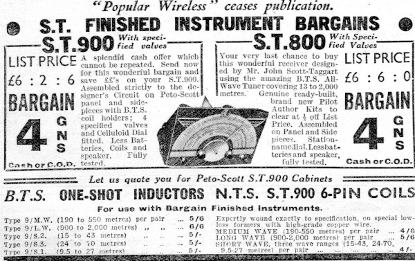
One radio that he certainly buit was the ST900, designed by John Scott-Taggart and described in Popular Wireless. The magazine included the blueprints and the dial scale was published as a centre spread, my dad bought a spare copy at the time.
In about 1962 we re-created this set. I don't know whether he had kept a duplicate set of parts or whether he had recovered them from his set.
The ST900 consisted of a plywood front panel about 15" by 12" mostly covered with the paper dial. At the centre of the dial was the dial pointer consisting of a metal disc about 3" in diameter with a long pointer soldered to it. To the right-side of the disc was the tuning knob under which was a sprung slipping disc arrangement that turned the main dial by friction. This meant that the dial pointer turned in the opposite direction to the knob.
The reverse of the front panel was covered in aluminium foil. We bought ours as cooking foil but at the time the radio was designed this was an item that came from the wireless parts shop! To each side of the front panel were attached triangular pieces of wood, so that the front panel stood sloping back at an angle. There was no back to the radio nor a base.
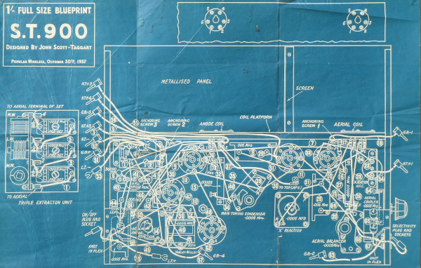
Across the rear of the front panel was a small wooden shelf, which braced the side pieces and also held two bases for plug-in coils. As I understood it, the previous design, ST800, had a coil pack and several switches. Scott-Taggart decided that switches were unreliable so he sought to remove them from the design. Thus to change waveband the coil pair was pulled out and replaced by another pair, hence the need for an open back. Similarly on the side was a flying lead that was plugged into a socket so as to form the on-off switch. Fortunately this was all set up on the large garage workbench so all the 'hot stuff' was pushed to the back of the bench up against the wall, well out of the way of small hands.
Construction was very much 'surface mount', the valve bases and items like large fixed capacitors were screwed to the front panel with wood screws and wire connections were made via screw terminals. Consequently there was very little soldering required, which would have made it quite easy to disassemble and pack away to build 30 years later. (I remember that we had to substitute one valve and it needed an adapter between it and the socket
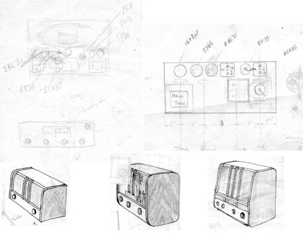
By the late 1930s the radio sets had evolved into sophisticated 'superhet' designs. After his grandfather died in 1934 my dad made a table radio set for his grandmother. Surviving sketches suggest that originally it was to have two control knobs but the final set had four, on/off, volume, tuning and tone control. I imagine that originally the plan was to combine the on/off and volume controls, quite a common practice, but then it was thought better to go for split controls as it was likely then that might be the only knob that his grandmother would need to turn. Although the cabinet survived it has no contents and it is not clear what internal design was eventually used, most likely a 4-valve one using, 5Y4G, EBL31, EF39 & ECA35 valves.
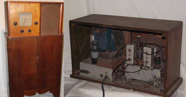
Following that a radio was made that 'plugged' into the top of a small wood cabinet. It's not impossible that the internal parts were recovered and re-worked from the set made for his grandmother as she died in 1939. I suspect that my dad made the cabinet for his grandmother's set but my aunt believes that the cabinetry for both these sets was carried out by their father, James Shaw . After he died in 1949 this set became our family radio until TV and FM radio took over. The cabinet was a convenient store for things like baby powder, which gave it a distinctive smell.
Post-war student
After my father completed his service with the RAF he applied to continue his interrupted studies at Herriot-Watt. I suspect that this gave him access to some metal working facilities that he didn't have at home. Equipment made around this time was housed in aluminium cases, rather than wood, and several of these had uniformly shaped louvres pressed out in them, suggesting that a proper press tool for that purpose was available at the college.
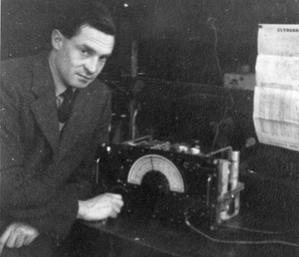
Photographs show my father working on an ex-RAF receiver, complete with the conversion instructions for civil use in the background.
During this period my father made a car radio, oscilloscope and a portable radio. He put a lot of thought into the mechanical construction of all of these. The car radio was probably intended to go under the dashboard of his father Vauxhall car, secured by its upper surface. Once the front panel was released the internal chassis, front panel and bottom of the radio unrolled, held together by hinges, becoming one long strip, fully accessible for servicing without removing the radio from the car. Having said that I don't think it ever got fitted to the car but sat around for some years in the garage and used as an extension loud-speaker.
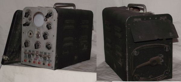
The oscilloscope was constructed inside a framework of aluminium right-angle section stock, modular aluminium chassis dropping into position and linked by plug and sockets. The left and right-hand side covers folded down, the rear cover had a lift-up flap which revealed the mouths of two tubes, into which leads could be pushed for storage. The front panel had a slot-on shell-like cover to protect the control knobs and screen. Like the car radio it was finished with a fine black 'crinkle' paint.
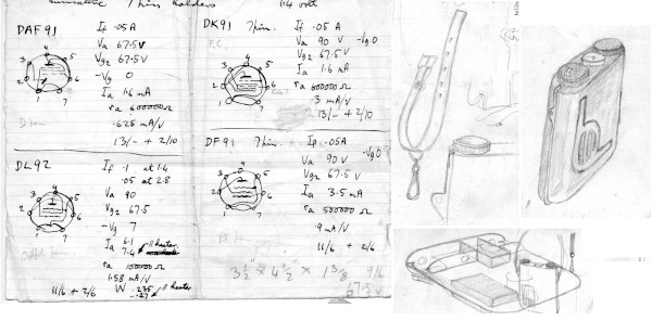
A this time my father was still courting my mother-to-be so he started making her a portable radio using miniature valves, powered by a dry battery, with an electromagnetic vibrator to generate the h.t. voltages. All the components were fitted to a central frame, allowing access to both sides and surrounded by a clam-shell, front and back. The upper edge of the frame carried the controls. A strap made from 300-ohm balanced pair cable formed a loop from one side of the control panel to the other. This served the dual purpose of acting as the aerial and a shoulder carrying strap. I rather think that this was another project that didn't quite make it to completion. Marriage, new job and new child, me, no doubt got in the way.
House Wiring
After moving to Birmingham to take up his new job with the Rover Company in Solihull my father's first priority was to work on the house and garden, in part to make it safe for his son and daughter on the way. The house had a mixture of large, round pin 15-amp sockets and the smaller two-pin sockets. None of these had the shields found on modern sockets. He made up wood boards, about the size of a modern double socket, to which was fitted an un-switched 13-amp shuttered socket and a slide switch by its side. These switches had a ribbed, ivory-coloured case with a black operating tap protruding from a vertical slot. Wired together as an assembly they were then fitted to the skirting boards, replacing the old sockets.
The kitchen was fitted out with two four-foot fluorescent tubes, set into a false ceiling. The starters were small glass bulbs that glowed blue as the tubes were switched on. It was quite unusual to have fluorecent tubes in houses at the time so visitors sometimes jumped when they came on as they associated the starting flicker with an unexpected lightning flash!
In later years one of the bedrooms was fitted with a concealed, up-lighting fluorescent fitting. It was wired up with five-way switching so that it could be operated by the switch at the door or one of four pendant pull switches. The idea was that the pull cords would only be fitted to two switches at a time, changed to suit the location of the bed in the room. This was carried out around 1962, I think.
Early Television
As a child I remember my father building his first TV. It used a 9" tube, which was pretty well that diameter throughout its whole length. A set of metal fingers around the circumference provided the connections when plugged into a socket like a bakelite dish. A rubber mask was pushed onto the screen end presenting what was to become conventional 4:3 rectangular screen to the viewer. I remember the TV being built into a plywood cabinet with four legs like plywood fins at the base. A large part of the chassis was taken up with transformers to produce the anode voltage for the tube. This made for quite a potentially dangerous design as the e.h.t. was consequently quite low impedance compared to more recent designs. My mum received a shock from this set while doing the dusting and there was a lot of talk at the time that she was lucky to have survived. My only memory of this set being used was of a lot of people sitting knee to knee around it and a cartoon of some ants sailing in a pea pod.
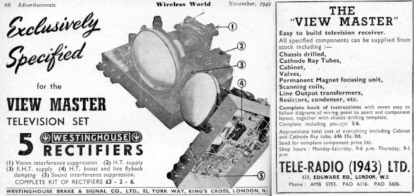
A year or so later on my dad built a bigger TV (12"?) based on a published design called the 'View Master'. He modified it by adding a radio chassis along the right-hand side.
In those days TV only started in the early evening so this meant that if the set had been used as a radio during the day switching to TV mode was quite instant, without the usual valve warm-up delay. The TV selector switch on the View Master chassis was ganged to the adjacent radio waveband switch with a couple of Meccano sprockets and chain. so that the chassis were quite separate mechanically and electrically. One of the controls was fitted with a sliding sleeve on the shaft so that by pushing or pulling the knob a lever was operated that pushed the operator of a latching push button switch inside the chassis. This switch operated a strip light fitted in a trough in the back panel so that the room could be up-lit by lighting up the wall behind the set.
This TV was designed to sit on a table and had a wooden cabinet that had been rubbed with some sort of white wax to bring out the grain. An old paint tin, painted black, provided cover for the protruding rear end of the cathode ray tube. (It was very rare, even for commercial TV sets, to have cabinets sufficiently deep to contain the tube without some sort of 'bulge' at the back). In practice the TV spent most of its life with the cabinet off. My dad always seemed to have to keep tweaking things with a wooden trimmer made from an artist's paint brush handle. For more complicated problems a set of modified Brandes 'earphones' or headphones were brought out as a diagnostic aid. The modification was a high-voltage rating capacitor in series with the headphones.
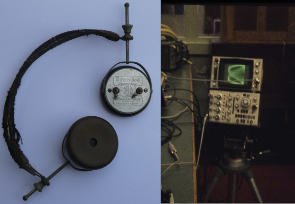
By 1971 I was to use the same headphones to diagnose TTL, integrated circuit logic, problems! It is a strange thing but the complexity of a fault seems to increase in direct proportion to the complexity of the test equipment available. My 'home' problems could always be fixed with a meter and the 'phones while at work it took hours trying to pick up nanosecond glitches on a state-of-the-art storage oscilloscope!
Both the home-made TV sets were single channel, BBC only, but then there was only one channel to receive. I think the Viewmaster continued in service into the early years of the ITV services on VHF Band III, which started for Birmingham in 1958, as in order to watch Popeye cartoons I had to visit my friend, David Farmer, living further up the road. Eventually Dad gave up on it and for quite some time we were without a TV altogether. Some years later we had a Bush set and then a KB 'portable', (it really needed two hands to carry it!).
With roll-out of BBC 2, using the UHF band, Dad was persuaded that it was better to rent from Radio Rentals. That set had spindly legs (that we had to buy) and the Band I/Band III turret tuner switch had a UHF position that allowed us to tune through the UHF band to find BBC 2, (in practice the UHF tuner stayed in the same position). We continued with this set until I bought my mum our first colour TV.
Relays and Buzzers
My father had a folding table, no doubt made by hs father, that he would set up in the living room when doing some of his electrical work so the smell of Ersin Multicore solder and the dangers presented by a hot soldering iron were things that we grew up with. (Some work would be carried out in the garage workshop that he made himself but soldering was a job mostly confined to the house).
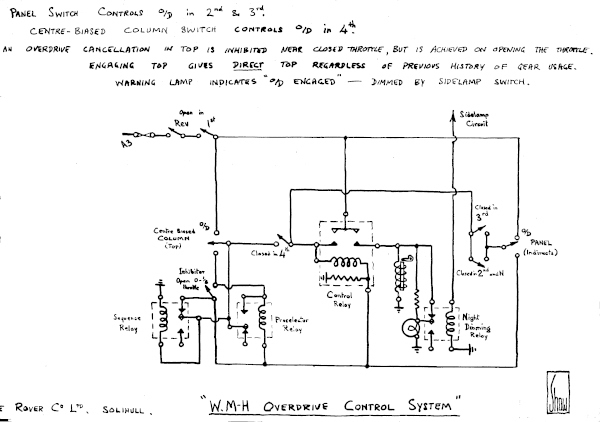
Until recently I wasn't aware of all of the electrical ideas related to the control of overdrive arrangements for Rover cars that he had been involved in. I imagine in those days that the people who looked after car electrics at the company were solely concerned about ignition, lights and instrumentation and not at all about control of the transmission. Did some of this work come home? I am not sure. Certainly by the time he started developing the overdrive scheme for William Martin-Hurst, for which he was joint patentee, the demonstrators and relay packs for that were constructed 'on the living room table'.
Having built a new garage and workshop my father built his own battery charger, constructing a rectangular, five-sided steel box which he painted red. I remember the red box being dunked into a bucket of water during the construction phase, no doubt he was rubbing down the first coat of paint before putting on a second. The open face of the box was covered with a piece of expanded aluminium mesh, which carried four rubber feet and which had two keyhole cut outs, so that it could be stored hanging from two screws on the garage wall. The charger contained a mains transformer and a large metal-oxide rectifier, a stack of square plates bolted together. It had a meter to indicate the rate of charging an on-off switch and a toggle switch for switching between charging 12 or 6 volt batteries.
With a growing family there had been a few instances of 'bed-wetting' and the treatment offered by the health service had been a rubber sheet and two aluminiumised sheets, one with large holes punched in it. These two sheets were laid on the bed, separated by an ordinary sheet, then connected to a white box containing a battery and a buzzer. The idea being that any bed-wetting would wake the child who would then realise what was going on. Dad didn't think it was very sensistive so he made his own circuit, fitted inside an old biscuit box fitted with four rubber door-stops as feet and with an old watch glass providing a lens for a light on top. I think the idea was that the child would wake in a partly-lit room, not totally in the dark, which would be more reassuring. There was a control switch which I believe was off the style fitted to the Rover P5 cars, the sort of thing that would have been used on the overdrive control project.
There would have been some sort of latching action and a couple of relays were used, one quite sensitive. No doubt this scheme could have been developed, but as it was it proved to be too sensitive as a sweating child could set it off. The bed-wetting stopped shortly after so the problem went away.
Hi-Fi and Heathkit
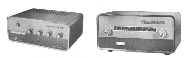
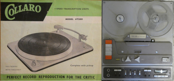
While my dad liked music I don't ever remember him actively sitting down to listen to it. This was the great age of 'Heathkit' or Daystrom in England. The basis of his Hi-Fi system was the S-88 amplifier, later uprated to S-99, (that is to say 9 watts per channel). This was followed by the F.M. tuner. There was talk of getting the Heathkit tape amplifier too and lots of leaflets were picked up relating to the various tape decks available. Records were played on a Collaro transcription deck. While the turntable was nice and heavy it was powered by the usual shaded-pole motor and rubber jockey wheel arrangement used on lesser model. The tape recorder problem was finally solved with the purchase of a Truvox PD-86 tape unit. This came with its own input and line output amplifiers so could be coupled directly to the S-88 amplifier.
All of these pieces of equipment were to be housed in a long narrow table with three compartments, amplifier plus tuner, tape unit and turntable.
Each section was to have a wooden lid supported with a gas strut. Although the struts were purchased I don't think we ever had any lids on it!. The ends of the table were nominally supported by typical sixties tapered screw-in legs. This might have been a bit whippy but below the table was a cupboard with two drop down veneered chipboard doors. The cupboard sat on its own legs and the 'table' was held above it on short brass tubes. In practice I don't think the long legs were needed or indeed ever fitted. The cupboard outlasted the top, which was never finished. In part this was because the equipment was always being hauled out to support public address duties at Scout and Church functions.
My father was a great believer in 'infinite-baffle' loudspeakers and to this end he bought two large 15" diameter loudspeakers whhich had a smaller eliptical louspeaker mounted across the centre. These were to be fitted to large trapazoidal baffles which would hang in the corners of the front room, as opposed to the living room. I don't think they ever were fitted to these baffles as two square baffles were made, painted the same colour of green as the outside of the house. These 'temporary' baffles were made especially for the public address use, the idea being that the loudspeakers would be moved from the house baffles to these public baffles as required. In practice Mum had to put up with these monsters, (but at least they weren't in the living room). Eventually Dad saw a couple of KEF K2 loudspeakers advertised, which he bought, and the green baffles were donated to the scouts. By then we had moved to a larger house and although the KEF units looked a lot better Mum was never really happy with them in the house. Despite the scouts having the old speakers I think the KEFs used to be taken to fêtes too, which resulted in someone poking a finger into one of the fibre cones. In the end I bought them a pair of Mordant and Shorts bookshelf speakers, something that Mum could live with and Dad agreed sounded OK
We did have plans to replace this set up with our own music centre using Sinclair Stereo 60 modules. The modules were bought, a wooden base made, the Collaro deck was covered in a new aluminium sheet to make it look 'modern. and the original arm replaced with a Connoisseur SAU-2 model. I made up some additional circuits to allow the tape unit to be plugged in. One way or another the project stalled and was finally killed when I bought Mum and Dad a Panasonic music centre.
More Heathkits
I think my dad really enjoyed building Heathkit equipment. They used quality components, everything was included and the instruction manuals often came with pull-out sheets so one didn't have to keep turning pages to read the instructions on one page and look at an illustration on another. Each step in the manual came with an empty pair of parenthesis into which one put a tick to show that it had been completed.
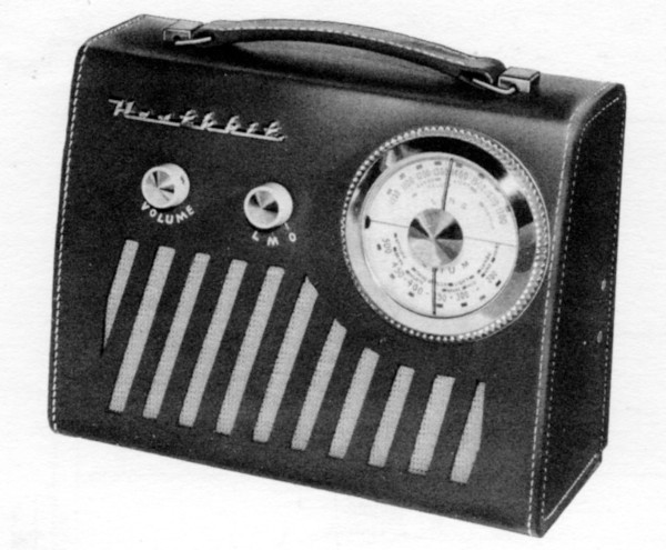
Although the hi-fi equipment was all valve-based Heathkit started to introduce transistor-based items. One of these was a portable radio, which was used by Mum in the kitchen. This radio was built into a metal chassis but came with a stitched brown leather case that was slipped over like a glove. The finished aricle looked as good as any commercial ready-built radio of the time and it gave good servce for many years.
Dad bought me a Heathkit transistor radio that was intended as a first radio - a sort of updated crystal set. It needed a long wire aerial and an earth connection plus a set of headphones, just like crystal sets did. In its basic form it had just one 'top-hat' transistor but there was an extra kit that Dad bought at the same time that added another 'top-hat' transistor to boost the output. Once I had built it I kept it beside my bed. (I remember listening to a programme by American singer Paul Robeson on it).
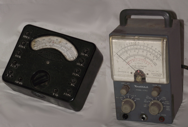
I am not sure why but Dad also bought and made Heathkit's valve voltmeter and r.f. probe kit. I can't say that I ever remember him using it, he was still more likely to use his AvoMinor meter, which, of course, worked instantly. I certainly used it a lot. I was able to take it to school once when I was studying A-level physics, we had been attempting to evaluate 'e/m' without success, as the laboratory voltmeter loaded the circuit too much. That was what a valve voltmeter was designed not to do and so with this meter we were able to get the 'right' answer! (I don't think either of use ever used the r.f. probe though, but as it was sold as an accessory for this meter it seemed sensible to buy it at the time.
I did consider buying the Heathkit oscilloscope as I thought one would be useful and for some reason the oscilloscope that Dad had made had been partially dis-assembled. In the end I bought an ex-Air Ministry Hartley 13A dual-beam oscilloscope, which weighed some 70lb and, because it used beam-splitting, the two traces had opposing polarities. (I also learnt not to hold the test leads when changing sensitivity settings as that could give one a sharp shock). I think the Heathkit model had only been single beam and I really wanted an oscilloscope that would allow me to compare two signals, which the Hartley did for, I think, a lower price but perhaps not so conveniently.
More Car Electrics - Brake Warning Schemes
The publication of Unsafe at Any Speed: The Designed-In Dangers of the American Automobile by Ralph Nader in 1965 led to European governments starting to legislate to make cars safer, one of the areas if concern was that of brake failure. Eventually this led to the adoption of various 'split' braking schemes in which more than one hydraulic circuit was required, from a simple front/rear split all the way through to complete duplication. Clearly it didn't matter how many hydraulic circuits were provided if the vehicle had no hydraulic fluid so as a first step car manufacturers started to monitor the level of the brake fluid in the reservoir.
Now that electricity circuits were being incorporated in braking systems it became worthwhile providing a warning that the handbrake was applied, many customers having forgot to fully release the brake, leading to excess wear or worse. My impression is that the various warning schemes either originated from the brake component manufacturers or the electrical/instrumentation department of the car manufacturer, in this case Rover. I say this because my father was clearly dissatisfied with the schemes in use as they combined hand brake and fluid level warnings, both of which the customer likely ignored.
As a result he developed various other schemes, ultimately producing a 'three level' system by which the driver could tell the difference between 'lamp testing', handbrake 'caution' and brake fluid 'danger'. The whole scheme never went into production but various elements did.
This was quite typical of my father's work as a development engineer, he would see a problem, perhaps in marketing, servicing or engineering outside his job description but would sketch out ideas for solutions. (After his death one of Rover's engine engineers complained to me that my father didn't appreciate that the engine, as the major component, got to be given the first choice of position. My suspicion is that he had probably pointed out that a minor change in engine position would make maintenance easier or make the integration of other, necessary, sub-systems a lot easier. He was certainly capable of seeing the vehicle as a whole, from design through to scrapping).
Home Computing
The arrival of the 'computer on a chip', the 8-bit microprocessor, making it a practical proposition for hobbyists to actually make their own computers without breaking the bank or giving over a basement must have seemed to my father something similar to the state of the motor car or radio in the late 1920s, early 1930s. As with early radio he started buying books about computers and taking magazines, such as Practical Computing right from its first issue in 1978. Various books on the BASIC programming language and products sold by the former radio hobby shop, Tandy, were purchased and read. Later on he attended a microprocessor course run for Rover.
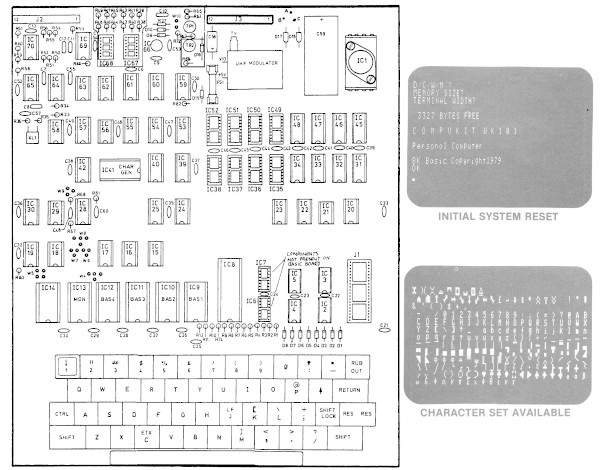
Following a period in Canada carrying out cold climate trials in Timmins, Ontario, he was given a tax rebate and used that as justification for buying a Compukit UK 101. This arrived as a large single printed circuit board onto which integrated circuit sockets were soldered, various resistors and capacitors, an analogue TV modulator and, on the lower part of the board, individual push switches to make up a keyboard. A separate mains transformer completed the kit, later versions supplied this in a sealed plastic module but his came in bare form. He assembled the kit and coupled it up with a small Russian portable black and white TV. At that time I was living and working in Scotland and he brought the whole lot up to me and seemed quite pleased with what he had done, demonstrating some of the programs that had been listed in the instruction booklet.
I don't think he ever ventured into programming on his own though. I wrote a few games and de-bugged a few from the magazines at the time and he loaded and ran these from cassette tapes. We had several very short tapes sold specially for that purpose, which stopped programs being 'lost' in the standard C60 tapes of the time. It isn't generally appreciated that programming really starts from a need, no-one just 'writes code' as they tell children nowadays. Although my father could see that the microprocessor would become more important in the future he could see that in the 1980s it wasn't going to 'run companies' and programming in machine code was hard work. In those days the press was full of horror stories like 'the million pound electricity bill' and the expression GIGO, 'Garbage In, Garbage Out' was known to a lot of people and conveniently trotted out by computing sceptics.
In his later years I provided him with a PC running Windows 95 but I think playing Solitaire was about his limit. I remember him coming back dispirited from a shopping trip because he had been unable to find the sheets of Letraset, rub-down lettering, for some graphic that he had in mind. The reason, of course, was that this product had been rendered virtually obsolete as 'any' font, in 'any' size was now available on the standard PC. In retrospect he probably investigated computing too early, at a too primitive stage, when one needed to be an enthusiast. Had he gone straight to a PC running Windows he might have been able to use his undoubted skills and talents. But then again, as with programming, he probably lacked a need, no longer taking a leading role in Scout and Church activities, other people now producing the publications that he would have done.
Conclusion
During his 83 years my father had taken his part in the beginnings of home radio, hi-fi and computing. Despite being a mechanical engineer by profession he had pushed for greater use of electrical systems in cars. At work he maintained a watching brief on developments relating to collision avoidance and anti-lock braking systems, the ideas were there but the technology was not yet up to the job or available at an acceptable price.
At home and at his church he designed and built his own heating control systems, the later mainly concerned with ensuring economy of operation and preventing heating the church all week. His dream was to design a scheme that varied the advance heating period depending on the outside temperature.
Just a couple of weeks before his death he was climbing out onto the single storey roof at his church so as to set up a demonstration of a closed-circuit TV system, retaining his interest in electronics to the end.