
Brakes - Design and Development Testing
Special Lecture given at Coventry Technical College, March 1965
Introduction
In 1965, from 4th January to 8th March 1965, Coventry Technical College, (now re-sited and re-named Coventry College), held a series of special evening lectures under the title 'Some Considerations of Motor Vehicle Design'. The course tutor was R.E.E. Streeter, A.M.I. Mech.E.
A course of ten lectures on motor vehicle design dealing in particular with those aspects influencing vehicle behaviour and performance.
This course is intended for designers and development and production engineers.
My father, Jim Shaw, was invited to give a lecture on vehicle brakes, the text of which is given below. The Rover Company was well represented as long-time colleague Jim Dodsworth was to give a lecture on vehicle heating the following week.
Note: During the lecture various slides were displayed. Unfortunately these have not survived as a complete set. Most of them had been borrowed so were returned to their owners, while the rest could have gone on to be used for other purposes. At the start of the lecture some illustrations and charts were handed out as additional notes. These still survive and are included within the body of the following text where mentioned for the first time.

The Lecture - 2nd February 1965
Having been in the employ of a vehicle manufacturer for about fifteen years and never having worked for a brake supplier - not deliberately, at any rate - my experience with brakes comes almost entirely from the installation and proving of other peoples’ brakes on what might be called our motor cars. In common with all other fields of design, compromise reigns over brakes, but since the availability of materials and techniques, the aesthetic and legal requirements, the weight and speed of vehicles, the density of traffic and the economies have changed with the march of time, so the compromises have changed and resulted in a variety of systems satisfactory to a greater or less degree for the vehicles to which they have been applied.
It is not my intention in this relatively short lecture, for such a big subject, to go through the entire history of brakes up to present day.
The title of this lecture “Brakes - Design and Development Testing” is not very restricting and the lecture, which I hope meets the terms of reference, deals with present day equipment and is broadly divided into four sections.
Brakes
First, Brakes. Brake is the term used for the complete mechanism fitted usually, but not necessarily, at the road wheel. Briefly a brake comprises the means of responding to a control force, and the friction surfaces, which are brought together by this force. The friction surfaces in contact provide the retarding force to be exerted at the wheel to which they are coupled. The energy stored in the moving vehicle is absorbed by the friction surfaces of all the brakes as heat, which is then, in turn, dissipated to the atmosphere. One of the friction surfaces is of metal and known as the brake track and deals with 90% of the energy, the other is a compounding of asbestos and resins, frequently with metallic inclusions, known as the friction material.
Brakes are currently of two configurations described as “drum” and “disc”. In the drum brake the brake track is the inner surface of a cylinder and the friction material, the lining, is riveted or bonded to the outer surface of a curved T-section member known as a shoe. In the disc brake the brake track is on both sides of a circular plate, or disc of metal. The friction material is a similar compounding of asbestos and resins frequently with metallic inclusions. It is usually riveted, bonded or moulded to a metal back plate to form an assembly known as a pad.
A brake drum has one closed side to connect the brake track concentrically onto the mounting flange of the hub or axle shaft to which it is spigotted. This closed side may be a one-piece casting with the brake track or a steel plate with the brake track cast onto it. The outer surface of the brake track will usually have a circumferential rib to stiffen the open side and this in conjunction with the back plate also provides a means of preventing the entry of surface water thrown up by the vehicle itself or other vehicles.
More than one rib may be provided to improve stiffness and cooling. Over-heating due to high duty or inadequate cooling is the bane of the drum and temperatures above 500°C can give thermal checking or blue spotting and heat cracking which usually shows up as brake judder. In borderline installations trouble from this can be avoided by bedding-in the linings before any high duty is imposed. Al-fin drums in which an aluminium drum to which a thin cast iron lining is molecularly bonded is a means of avoiding this thermal stressing in the brake track and providing improved cooling.
The back plate of drum brake is mounted on the stub axle or the axle casing and it carries the lined shoe assemblies and their mechanical and/or hydraulic operating systems. The ends of the shoe react on pivots or sliding abutments, which are provided, on the ends of other shoes or hydraulic pistons or adjuster mechanisms or off the back plate.
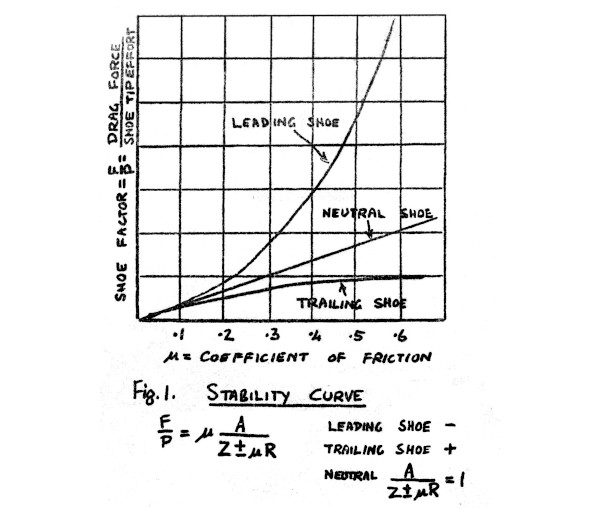
A shoe is a “leading shoe” or a “trailing shoe” depending entirely on whether a point on the rotating brake track passes the free end of the shoe before it passes the fixed end (having traversed the shoe in the meantime). If the point passes the free end first, the shoe is leading, if the fixed end first, the shoe is trailing. Clearly a shoe, which is leading for forward motion, will be trailing for reverse motion and vice versa. A leading shoe has a self-wrapping or self-applying tendency and less shoe tip force is required to produce a given drum drag with a leading shoe than with a trailing shoe.
The ratio of the drag force F (exerted tangential to the brake track) to shoe tip effort P is called the “shoe factor” and an expression of the form

(where A, Z and R define dimensions of the particular brake.) defines the shoe factor where the negative sign is applicable to the leading shoe brake, positive to the trailing.
From this simplified relationship it can be seen that not only is the shoe factor of a leading shoe greater than that of a trailing shoe with all the factors equal, but the leading shoe is unstable if μ is allowed to rise. This at once points up the advantages and disadvantages of the two types of shoe layout. The leading shoe gives a powerful brake for minimum actuating force and can give light pedal efforts without recourse to power assistance - it is a self-servo brake. If it is subjected to high energy inputs without adequate cooling its drum and lining temperature will rise and if, as is the case with most linings as temperature increases, at – least in the higher ranges, the μ or coefficient of friction will fall. This falling coefficient or fade has an exaggerated effect on the performance of the leading shoe brake and leads to its rejection for high duty applications where adequate cooling and/or stable enough lining coefficients are difficult to obtain.
The trailing shoe although requiring more effort to operate it, is very tolerant of linings which fade and in fact masks their deficiency. It has the disadvantage that power assistance becomes a necessity at lower vehicle weights.
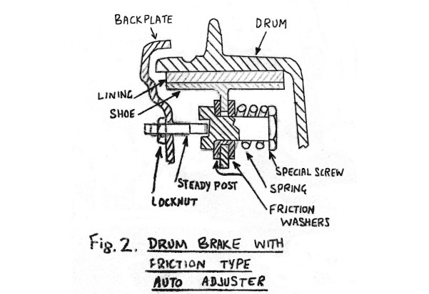
Drum brake practice is to use a pair of shoes in a drum and the three obvious combinations of the two basic shoe actions have been and are still used. Thus there is the “two leading shoe brake” which has two “wheel cylinders”, as they are called, mounted diametrically opposite on the back plate with their axes parallel. The cylinders are single acting and the closed end of one cylinder forms the fixed abutment for the shoe, which is actuated by the piston of the other cylinder. This brake may have manual snail cam adjusters – one for each shoe - or it may have ratchet type auto adjusters. It will look at first glance something like the brake shown in this slide, but this brake is, in fact, the second obvious combination - the “two trailing shoe brake”.
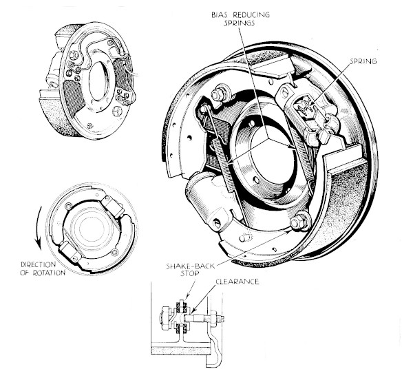
This particular example, of Girling manufacture, is self adjusting through the action of spring loaded friction wasters mounted on a link pin with a recess in the end giving diametrical clearances over the end of the steady post mounted on the back plate. The diametrical clearance is of course, the designed shoe centre running clearance. “Two leading shoe” and “two trailing shoe” brakes are used as front brakes, the latter with servo assistance.
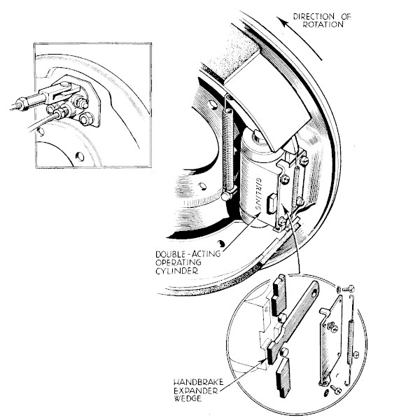
For a rear brake where there is a handbrake requirement in addition to the service brake duty it is desirable to use a brake with approximately the same drag in each direction for a given input effort and the third combination the “leading and trailing” satisfies this requirement. “Leading and trailing” brakes can also be used as front brakes. The slide shows the Girling HW brake with its double acting wheel cylinder and double acting screw/wedge adjuster. The slide shows the handbrake - operated wedge, roller and tappet mechanism mounted on the side of the wheel cylinder. The draw link projects through the back plate to be picked up by the handbrake linkage.
Lost travel - in the sense that it is wasted — and which of course shows up as increased travel, is not a good thing in a brake system especially when it occurs during a stop. The drum brake is prone to this defect. The action of the shoes tends to lozenge the drum, open the mouth across the shoe centre diameter and close it on the diameter normal to that. In addition during a stop it expands thermally away from the shoe, which has to follow it up matched by the brake pedal travel. If, as happens, especially with the “two leading shoe” brake, there is lining fade or drop in μ, which requires heavier effort to maintain the deceleration required, this too increases the travel. The slide shows a comparison between a drum and disc brake the latter will of course have a tendency the other way but this is in fact, very slight, being on a small thickness of disc of the order of ½ in whereas the drum diameter will be of the order of twenty times - in the other direction.
In the disc brake shown, the disc with a small offset to the flange, which mounts it to the hub, can be clearly seen. Note also the antisqueal damping ring in a groove on the edge. To work, damping rings need to be just so - not too tight and not too slack. In service they can easily become too tight - due to rusting or too slack due to high temperature working. A cheaper, simpler and just as effective method of controlling squeal is to use a shim of the shape shown between the piston and the pad back plate, The same effect can be got by stepping the end of the piston or by arranging the pad offset to the piston. The caliper shown is of course, cut away to show arrangement of the parts. The caliper is cast in an inner and outer half, the inner having the mounting lugs to pick up on the stub axle. The two halves are bolted together and internal drillings convey the brake fluid to the cylinder in each half. The dust seal can be seen between caliper body and piston also the hydraulic seal, the inlet port, the bleed port, the pads with their metal back plates and the pad retaining pins.
The metal back plates of these brake pads extend beyond the lining material and take the drag reactions onto the calipers. It is possible in certain installations, with caliper and pad tolerance clearance build up to have pad rattle and this can be controlled by fitting anti-rattle springs carried by the retaining pins or integral with the antisqueal shims. The caliper shown is a Girling type 18. This slide shows how seal distortion or roll back tends to retract the piston to allow a running clearance.
This slide shows the parts of a Dunlop Mk.2 caliper, which differs considerably in design from the Girling. The body is a skeleton, which carries separate wheel cylinders. A range of diameters is available The pads thrust directly onto the body and have thin back plates with key hole slots to engage with the mushroom peg on the piston and which is formed into a platform to support the pad. A pin, spring and friction bush connect the piston to the end of the cylinder and act as a retraction device to give the pad a positive running clearance to the disc. The operation of the retractor is similar to the operation of the auto-adjuster fitted to the two trailing shoe brake mentioned earlier, although the details of the mechanism are quite different.
The pads are retained by a keep plate fastened to the central bridge. An external pipe is necessary to connect the two cylinders. This slide shows the assembled caliper, part cut away, with a disc. This disc has a more offset mounting than that previously shown but no significances attaches to its being shown with this caliper. The amount of offset arises largely from considerations of the geography of the layout of wheel rim and nave, the steering swivel and suspension links, although a deeper ball can be beneficial in providing a larger heat path from disc to hub bearing resulting in the ability of the installation to tolerate higher disc temperatures without melting the hub grease. Discs mounted well inside the wheel will not be so easily cooled although the outboard pad will be better shrouded from road dirt and water.
Consideration of the forces acting, in side elevation, will show that a spot caliper mounted in front of the axle increases the loading on the wheel bearing to a considerable degree.
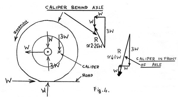
In the case of a caliper on the horizontal centre line of the disc where the effective radius of the brake is little more then 1/3 the wheel rolling radius the vertical load increase will be nearly 3 times the retarding force at the road. If a tyre/road coefficient of 1 is available and utilised, the forces on the bearing would be W vertical due to the weight on the wheel during braking (including weight transfer), 3W vertical due to the torque reaction and W horizontally due to the retarding force at the road being transmitted to the vehicle, the resultant on the bearing would be over 4W.
With the caliper transferred behind the axle the magnitude of each component would be as before but the vertical force due to the torque reaction would be in the opposite direction and the resultant would be about 2W. Rear mounted calipers are, of course, more shielded from road dirt and water but the inboard side of the disc and caliper may still be showered with road dirt and water from the opposite wheel. In general the performance of the disc brake is little affected by operation in wet conditions indeed the effect of road grit can be to increase the brake drag for a given input.
Occasionally a complaint of initial ineffectiveness is heard from a wet-motorway user who has travelled a long way without using the brakes and this may be the conjunction of low cold μ from which many linings suffer to a greater or less extent and water soaked pads. This condition when it occurs always seems to disappear very quickly and does not seem to be easily reproduced at will. The effect of grit laden water can be more serious and it is possible to slice off pad material very rapidly by running in adverse conditions without use of brakes.
This is known as “wet abrasion” and usually affects the inboard pads more than outboard. In its milder form differential pad wear will be observed but, uncontrolled the phenomenon is quite uneconomic. To combat this it is now common practice to fit dirt shields to disc brakes. A variety of dirt shields have been used. A flat plate mounted ¼ to ½ an inch from the disc. A flat plate with a lip or flange extending partly over the disc edge with the flat plate anything from ¼ inch to 1 inch away from the disc. A flat plate with a flare towards the disc - or away from it. ‘Flat plate’ is perhaps not the best expression to use since the plate has to be formed to clear steering swivels and ball joints, suspension joints and, of course, calipers. It is quite easy to overdo dirt shielding and adversely affect the cooling of the disc.
Only by practical testing is it possible to decide whether a satisfactory compromise has been reached between the demands of wet-abrasion avoidance and cooling with, of course, an economic solution. Calipers are sometimes provided with coverplates to exclude dirt. This slide shows a Dunlop Series 3 caliper, which can be provided with a cover plate. This caliper differs in construction from the Dunlop caliper shown previously in that one cylinder is integral with the body, there is no bridge piece over the disc periphery, the pads are retained by a single pin similar to the two used in the Girling brake, the pads have thick metal back plates but reaction thrust is still taken on the pad material. The abutting face of the caliper is, however, a loose piece and can have special anticorrosion treatment, which need not be lavished on the rest of the caliper, unlike the Mk.2. The complete brake with a disc is shown in this slide without the cover plate. The cover plate for this caliper is shaped to form a travel limit to the pad when it is considered to be worn out. This is a similar feature to that provided in the Mk.2 caliper by different means namely the abutment provided in the body against which the piston is arrested.
The Girling brake did not have such a feature and could in fact wear out the back plate as well as the friction material. Opinion is divided on whether this or the positive stop is the better. The Girling method may lead to costly replacement of discs whereas the Dunlop method relies on the driver observing “pull” initially, leading to less and less effective brakes. Neither method seems infallible. A noise generating insert in the lining could be a very effective indicator of pad life ending but it could only be completely successful if noises from the brakes were otherwise unheard of.
Proposals have been made to indicate wear-out electrically by means of a contact embedded in the pad but so far we seem to be prepared to hope for the best with the two systems mentioned. Many cars are satisfactorily braked with a disc front, drum rear combination but others for performance or sales gimmick reasons have discs all round. A disc handbrake must therefore be provided and the slide shows the Dunlop Mk.2 handbrake caliper on the end of a Mk.2 service caliper. This provides leverage within itself as shown of about 15:1. It is provided with an automatic adjuster of the ratchet type. The retractor fork can be seen on top and operates on the principle that the permanent set is always less than the travel.
A recent modification pivots or articulates the retractor fork centrally between the pivot pins and makes the brake more tolerant of end float without pad squeak effects. This slide shows the Mk.2 handbrake caliper on the end of a Series 3 brake. This slide shows the corresponding Girling mechanism. This slide shows the Dunlop Series 4 caliper which uses the same pads for service and handbrake. It is in fact, a mechanical caliper for handbrake use, operated by a separate hydraulic cylinder for service brake use. One double acting cylinder can be used to operate a pair of brakes.
Actuation
Next Actuation. Actuation embraces the remainder of the brake installation not covered by the first section or in other words that part of the system, which accepts the driver's control effort and transmits it with the necessary leverage changes or power assistance to the brake as a control force. For many years the driver’s effort was applied invariably through a pedal pad and stalk on to one end of a first order lever located under the floor, the other end of the lever operating rods or cables embodying compensation systems to ensure balanced action at the brakes.
The rods and cables gave place to the hydraulic system with its inherently balanced effort-transmission and its ability to provide leverage changes readily.
The underfloor installation in its turn gave place to the pendant pedal under the scuttle. The pedal pad is now usually on the end of a second order lever with a push rod output taken off horizontally or slightly elevated below the pivot although a bell crank layout can also be used with the push rod taken off vertically or almost so. The push rod will usually act on the piston of a master cylinder. Master cylinders can be typified by their recuperation systems. This slide shows a Girling CB type master cylinder. With the piston back (brake released) the fluid in the cylinder is in communication with that in the reservoir and the system is recuperating. Forward movement of the piston shuts off this communication and further movement displaces fluid into the system. With the system under pressure and the reservoir-fluid now communicating with the back of the recuperator seal the back seal is still called upon to retain the fluid in the reservoir.
This slide shows a Girling CV type master cylinder. In this type the recuperator valve is at the end of the cylinder. The reservoir may be cast integral as in this case or a pipe connection for a separate reservoir can be catered for. The integral tank has a sump formed below the level of the inlet port to act as a dirt trap. Additional protection against dirt entry can be provided by fitting a nylon filter. A translucent nylon extension can be fitted to the top to allow visual checking of the fluid level without removing the cap. Alternatively, low fluid reserve can be indicated by an instrument panel warning light energised via a float-operated switch mounted in a special cap. To keep the warning light checked some vehicles are wired so that another parallel switch is operated “off” by the handbrake on its last click in the off direction. This can lead to the low fluid level signal being interpreted as “the handbrake switch has gone out of adjustment, I must have it seen to – sometime –”.
It would seem worthwhile to avoid the possibility of such a misreading by having a resistor in the handbrake switch circuit so that handbrake “on” and lamp checking signal would be at a lower level of brilliance than the less frequent, though more vital, “fluid low” signal.
Where vertical or near vertical mounting of the master cylinder is required integral reservoir units of both types of cylinder can be obtained with the relative axes of the cylinder and reservoir suitably adjusted. Another type of recuperator system is the “tipping valve” used to a great extent in tandem master cylinders. In this case the valve axis is normal to the cylinder axis and the jumper is spring loaded onto the seating when the master cylinder is delivering pressure.
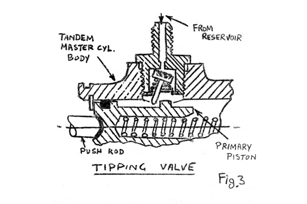
The tail of the jumper is contacted by the back of a step in the piston when it returns to the off position. This tips the valve off its seat. The tandem master cylinder provides in one unit for the simultaneous operation of two separate hydraulic systems which is considered by some to be a valuable safety feature, The obvious split between front and rear brakes is frequently used but other splits such as the diagonal, where a left front and right rear are coupled and vice versa or the provision of two brakes per wheel actuated simultaneously, but independently, has been used.
The tandem master cylinder can have a single bore, mandatory, of course, in the two latter systems which have symmetrical requirements. For front and rear splits a single bore can be used but the availability of differential bores can be made use of to provide some or all of the distribution difference required between front and rear brakes. This slide shows a typical single-system piping layout with a pendant pedal operating a CV type master cylinder feeding pressure to a five-way union which accepts a pressure operated stop light switch and bundy piping feeds to each front and the rear brakes. Reinforced rubber jump hoses carry the pressure from the piping fixed to the sprung vehicle to each unsprung, front-stub-axle-mounted brake and to the rear axle where a three-way union supplies bundy pipes feeding each rear brake. On cars which, for reasons previously discussed, require assistance to augment the driver’s effort, this is usually provided by an engine vacuum powered servo-motor or booster.
Such servos can be hydraulic or mechanical, the former boosting the pressure from the master cylinder and the latter boosting the pedal effort applied to the master cylinder. The hydraulic servo is sometimes called a “remote” servo and the mechanical a “direct-acting” servo. The hydraulic servo shown in this slide is the Girling AHV 689 unit,
It is customary nowadays to arrange this type of servo to be vacuum-suspended. This means that both sides of the air piston are quiescently under the influence of the vacuum level stored in that part of the vacuum system (which may include a reservoir) separated from the engine induction system by a non-return valve. In this unit input pressure from the master cylinder is in communication with both side of a differential piston, which thus unbalanced moves and rocks the air valve closing first the vacuum part and then opening the atmospheric part. This action leaves the front of the air piston subjected to stored vacuum but exposes the rear of the air piston to atmospheric pressure. The air piston, now unbalanced, moves so that its piston rod first closes communication between the opposite sides of the differential piston. Further movement increases the pressure on the output side of the slave cylinder piston and this pressure as well as being communicated to the brakes, is applied to the small end of the differential piston. It thus attempts to regain balance and shuts off the atmospheric air port when balance is reached.
Balance can of course, be attained over the whole range of input pressures from cut-in pressure of the order of 40 lb/in2 up to the point where the air valve cannot close because full use is being made of the available pressure difference between atmosphere and stored vacuum. This latter is known as the “knee point” which name arises from the shape of the graph of output/input pressure for the servo. The slope of the graph between cut in and knee point is usually of the order of between l ½ and 4 to 1. The slope of the curve beyond the knee point is less than that before cut in (direct master cylinder operation 1:1) due to the loss of slave piston area incurred by the presence of the push rod. Ideally one would use a servo big enough to avoid operation beyond the knee point, for deceleration up to 28 ft/sec2 at least, but economics and the need for a high boost ratio sometimes force the acceptance of knee points as low as 16 ft/sec2.
The corresponding Lockheed servo uses a rolling diaphragm instead of a piston and the pressure admitted behind it by the control valve is also used on the control valve diaphragm to balance the input hydraulic pressure. Apart from this difference the operation is similar. Since both have seals with vacuum one aide and hydraulic fluid the other both are potentially liable to suck hydraulic fluid out of the hydraulic system into the vacuum system and, the engine. The propensity of this type of servo to do this has been much reduced by careful design, manufacture and quality control, but nevertheless can still cause trouble. This slide shows a system using a hydraulic servo. The stop light switch is in a 3-way on the servo input side but it could equally well be in a 5-way on the servo output side - a 5-way being substituted for the 4-way shown. A stop light switch on the input side obviously has an easier life but on the other hand it will not give such a low acceleration stop signal. A micro-switch on the pedal return stop could give the earliest warning of a stop to a following vehicle and avoids a potential hydraulic leak.
The direct acting or mechanical servo has a vacuum supply direct to the front of the air cylinder, which is always under vacuum. A port through the centre boss of the rolling diaphragm or piston communicates with the control valve mounted on the other side. The control valve body extends through the back wall of the air cylinder and an annular seal is provided between them. Behind the seal is an annular air filtration and inlet system to the valve. The input push rod, for connection to the brake pedal, goes up the centre of the valve to push on the centre boss of the rolling diaphragm when its clearance is taken up. Taking up the clearance initially, closes off the vacuum feed from the front of the diaphragm and opens the air valve allowing air to enter the rear of the cylinder. Pressure difference across the diaphragm provides the assisting force which added to the input force is carried forward by an output push rod operating the master cylinder carried on the front of the booster. Of necessity this type of servo must be mounted within striking distance of the brake pedal to avoid complex linkages with their frictional and economic disadvantages. It is not always easy to install this type of unit on a vehicle which has not been designed with a direct servo in mind and when a new vehicle is being designed around a direct servo it tends excessively to influence the layout of the vehicle. With the trend towards reduction of pedal effort and travel, vacuum servos to match this tendency can only get bigger since they operate from a limited pressure potential. This increases the difficulty of installation and increases it more for the direct than for the remote unit. However, the direct unit is simpler and cheaper and cannot present the engine with the opportunity to swallow the brake fluid. The vacuum source for all the boosters mentioned is almost invariably the engine induction manifold. Diesel engined vehicles, of course require to have a vacuum pump usually engine driven. The actual position of the off-take will usually be decided by the engine designer or development engineer and may be at one end of the manifold or central. A rising off-take is desirable, even essential and downward off-takes should be shunned. Since the booster will usually be lower than the off-take the vacuum pipe will have to fall towards it over part of the run, at least, and it is advisable to allow the run to drop below the booster connection and therefore have to rise again to reach it. The aim is to keep petrol out of the booster - rolling diaphragm boosters are especially vulnerable as their diaphragms must be of flexible mix which perversely will not usually withstand petrol attack without embrittlement and cracking. Even with piston types, which are more tolerant, petrol trapping in the servo should be avoided. The non-return valve, essential to store vacuum at the higher levels reached by the varying source, has a part to play in the exclusion of petrol from the system. It cannot of course, keep petrol out during its open phases, that is, when the system is re-charging and it should be fitted in such a position that petrol cannot condense and be held back by it when it is closed only to be released into the vacuum system when it opens. Since the valve jumper, which may be a flat disc or hemispherical, must seat well enough to hold 11 - 13 lb/in2 with a low seating force it is usually of rubber and since even good petrol resistant rubbers are not absolutely inert, it seems a good idea to put the NRV near the servo and rely on the rise-fall-rise run to keep petrol away from the valve, however, recent experience is that even with such a system, petrol can still get through. It seems that a combination of all the points mentioned, namely, manifold - NRV - rise-fall-rise - NRV - servo is the best that can be offered.
Vacuum servos lend themselves readily to operation from an air pressure source either with or without retention of the vacuum supply. This offers the possibility of reduction in servo unit size even in spite of catering for reduced effort and travel. Economics militate against the use of such an expedient at least- until an air pressure source becomes necessary for some other vehicle system such as suspension levelling or exhaust purification.
Any trend towards the use of a centralised fluid power source, be it pneumatic or hydraulic, can involve the brake system if the most economic design of the vehicle as a whole is to be achieved. There is no doubt that power hydraulic systems for steering or brakes utilising flow-restriction to obtain pressure as required readily provides the smooth transition from “off” to “on” essential to refined control. The possibility of operating two or more such systems from a single pump although attractive is, I am convinced, fundamentally unattainable. A ganged pump, with “X” sections for “X” systems could apparently overcome the difficulty, but an “X” ganged pump is not a single pump and although it might be cheaper than ”X” pumps it is bound to be more costly than a single pump, A hydraulic pressure system on the other hand can supply any number of utilities but the finesse of the flow restriction system over the “off – on” transition is difficult to match. Power hydraulic systems of either sort have the bonus advantage from the brake viewpoint that they eliminate the possibility of system failure due to local fluid vapourisation and can sustain brake operation even against a leaky system. They make frugal space demands in the bulkhead area and although otherwise not as versatile as a remote vacuum servo, since the pump has to be provided with a drive, they off-set this by being less bulky.
Brake Distributions
Brake Distributions: Anyone who has ever gone downhill on a bicycle and been a little over enthusiastic with the front brake will have realised that weight is taken off the rear end even beyond weightlessness and on into orbit. This same tendency occurs in all vehicles under braking although overdoing it on the front is unlikely to have similar consequences since unlike the bicycle and rider, the C of G of a vehicle is usually further behind the front wheel than it is from the ground. On the other hand overdoing it on the rear of a vehicle can have equally disastrous results, although in the horizontal plane rather than the vertical. The braking force which can be applied to a vehicle through a wheel depends on the weight on the wheel during braking and the coefficient of friction between the tyre and the road. The tyre/road μ can vary considerably. Under icy conditions it can be less than 0.1, in the best conditions it can be as high as unity.
If the tyre slides on the road the drag force will usually be considerably less than that which can be achieved just as wheel locking is reached. There is, therefore no point in applying more brake torque than that able to lock the wheel under the conditions of weight and friction obtaining on any specific occasion. Since the change in weight on the wheel is proportional to the deceleration and it is not easy to provide for the varying braking ratio which ideally is required a compromise is made. Where W is the vehicle weight and B (the braking force) is WF static front weight, WR static rear weight, H, centre of gravity height, and L the wheelbase. The weight transfer is BH/L and the front wheel weight therefore becomes W + BH/L and the rear, of course, WR - BH/L, the total weight on the wheels remaining constant. Individual designers will use this relationship to decide the braking ratio in conjunction with some other specification such as that brake distribution should be correct laden, two up at 28 ft/sec2.
Any fixed compromise will of course, result in less than the maximum performance under some other condition of loading or tyre/road adhesion. The specification mentioned would result in premature front locking in slippy conditions. Front locking results in loss of directional control, but the vehicle slides in the direction it was moving at the inception of the slide. Rear wheel locking is a state of unstable equilibrium however, and any lateral disturbing force such as camber or cornering will start the vehicle rotating about the front wheels unless they have already been locked. It is not easy to arrange correct distribution throughout the range of decelerations encountered, but means have been proposed of preventing wheels from locking.
Undoubtedly the most sophisticated of these is the Dunlop Maxaret system which prevents any wheel to which it is connected from locking at whatever deceleration (tyre/road μ) it occurs. It is designed for use on a power hydraulic system of the pressure type. An anti-skid unit, is fitted at the wheel. The wheel drives an inertia controlled valve contained in the anti-skid unit which opens and releases brake fluid back to the reservoir, if the wheel should try to lock, that is attempt to decelerate the flywheel at just over lg. A Modulator which normally provides no restriction in the line reacts to the resultant pressure drop at the brake, with the input pressure maintained, by restricting the flow of replacement fluid and regulating the rate of pressure re-build at the brake. The system oscillates to arrest and release the wheel at locking point. Its original and present use is on aircraft but car installations which have been tried are too costly for popular use.
Various lower cost and less effective proposals have been made. Lockheed have a pressure limiting valve which shuts off the rear brakes from further pressure increase at a set pressure. They also have a “g” operated shut off valve. Kelssy Hayes have a pressure operated valve which doss not shut off but allows the pressure in the rear line to continue to rise but at reduced rate relative to the input or front line pressure.
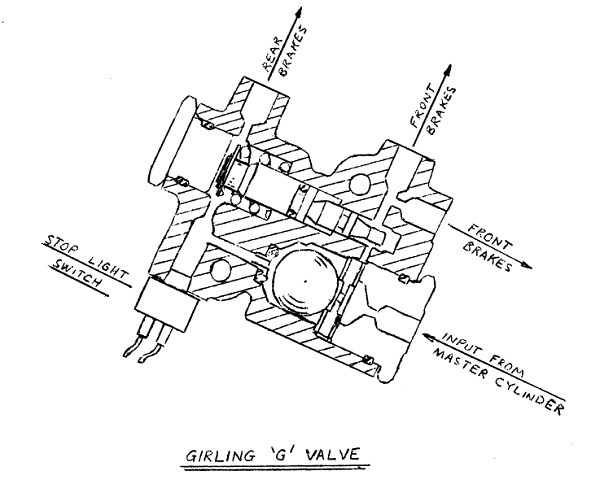
Girling have a similar valve which is “g” operated. Not having a slide, a diagram of the unit has been circulated. This unit has been designed to replace the 5-way union which is, or could be, common to most brake systems. It is set at an angle on the vehicle so that a deceleration of about 0.3g. will cause the ball to close the front - rear communicating port - that is, at an angle of tan-1 0.3. The differential diameter control piston will now adjust its position rearwards and drop the pressure in the rear line. Further input pressure increase will cause the control piston to reposition itself to raise the rear pressure by the amount necessary to rebalance it.
Lockheed have also “anti-lock” device which consists of an inertia valve driven off the transmission of a rear wheel drive car. This valve unlike the Dunlop Maxaret valve controls air which in turn acts on a rolling diaphragm servo unit, which is supplied with engine vacuum. The servo unit when energised shuts off the rear brakes and increases the volume of the rear system which reduces the pressure and frees the locking wheel or wheels. This system like the Maxaret will oscillate at incipient locking. The slide shows conveniently something of the problems now feeing considered. The vertical scales marked in % weight, Rear on the left - Front on the right and the horizontal in fractions of “g” deceleration. The lines show the % distribution required ideally throughout the range of deceleration for two loading conditions. The horizontal line shows the chosen compromise and how it is correct at one point on each of the ideal curves.
A Maxaret system would of course, by never allowing locking to occur, effectively give correct distribution for all conditions of loading or tyre/road μ provided that the distribution chosen was sufficiently rear ended to cater for the most rear ended distribution required - in this case 48% on the level. Downhill, additional weight would be transferred onto the front in proportion to the gradient (tangent) and this has the effect of lowering the ideal line by the percentage gradient. Uphill the effect is, of course, reversed. The pressure cut off valve would cut in at a point on the distribution line chosen at a line pressure equivalent to a level road deceleration and would then cause the distribution line to fall, the earlier the cut in the steeper the fall. A distribution could be chosen to make the droop follow the two up condition but it would still not result in a very much better compromise. The “g” operated cut off is no better on the level but it does tend to compensate for hill braking. The “g” operated pressure transducer can more nearly match the slope of the ideal line and compensates for hills.
The Lockheed anti-lock system tempts the radical step of using the distribution calling for the highest percentage rear braking ever required and relying on the system to give effectively correct distribution throughout the decel range. Apart from preventing rear locking, used in this way it can provide better decels in low μ conditions and shift some of the work from the front to the rear. The amount which can be shifted is not insignificant, if a 75:25 ratio is changed to 50:50 the front duty is reduced 33⅓ %. The rear duty would of course be doubled. In passing, the energy involved and rate of working have not been mentioned. The energy stored in vehicle of 3,000 lb weight at 100 mph is 2,000,000 ft.lb. and this is sufficient to melt 5 lb of iron! But not to worry, the front discs would weigh about 10 lb. each and rears about 7.
To stop this vehicle at 0.75g represents an initial power of 600 hp and a mean power throughout the stop of 300 hp.
Testing
Testing: The testing of brake systems can have many facets. Proving tests, defect investigation tests, performance tests, rig tests, road tests, endurance tests, fade tests, wear tests, etc., etc. The extent to which a vehicle manufacturer’s engineers are involved in these will depend on that firm’s policy. The most basic test is that of deceleration performance in which the decels produced by pedal efforts over the full range of deceleration are recorded. This test is usually conducted on a dry, level concrete or tarmac road.
The decel is indicated on a U-tube gauge mounted by rubber suckers on the windscreen and pedal effort is applied through a pressometer usually consisting of a hydraulic piston-in-cylinder transmitter connected by a reinforced rubber hose to a pressure gauge calibrated in lb. pedal effort, The best equipment is tolerant of non axial effort application and the gauge will have a system-volume zero adjuster to allow correction for temperature effects, rubber hose routing or leakage. Alternative equipment, such as the pendulum decel meter and the strain gauge pressometer can be used.
Pedal travel may also be required and can be recorded by a “string on a spring-loaded-reel” instrument which has a free member zeroed each, application and carried round by the reel and left on release to indicate maximum travel. Some testers prefer to work with a line pressure gauge rather than a pedal pressometer but it is not always convenient to install a line pressure gauge and the final answer will usually be required in pedal effort whichever method is used. It is essential to run through the decel test at one brake temperature - cold, which usually means under 100°C. and from one speed usually 30 mph. and with the engine disengaged.
It is sometimes preferred to measure the stopping distance rather than the deceleration and this is done by firing a chalk marker onto the road at the start of pedal movement and measuring the distance from the mark to the vehicle rest position after the stop which is obviously a more laborious and time consuming method. This technique is of greatest importance when exploring the ultimate performance in different conditions of road/tyre friction. The same information can be got more easily by towing a 5th wheel arranged to transmit a number of electrical impulses each revolution and starting a pulse counter by pedal application as before.
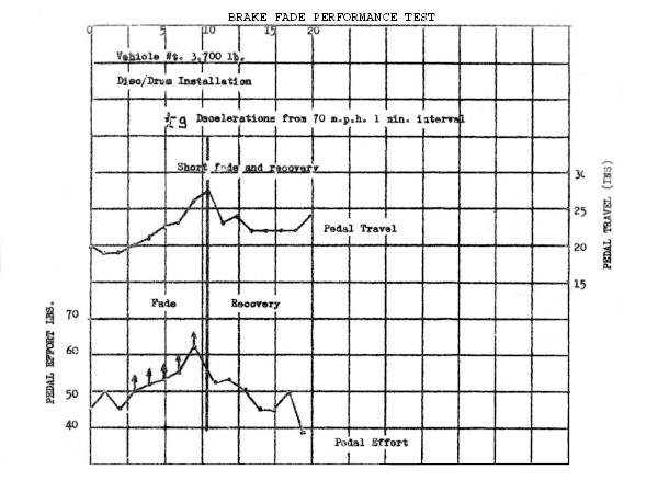
The other main routine test is the fade test and recovery conducted in short and extended forms. In this test conducted from a speed of the order of 80% of the vehicle maximum, stops are made at intervals - usually 1 minute, at 0.5g deceleration. The pedal effort and travel are noted on each stop and variations within the stop. The short fade consists of 8 stops and the extended fade 40 stops. The fade section is followed in each case by a recovery test at 30 mph. Fade testing is less standardised than decel testing and other intervals are sometimes used. Some testing is done at constant pedal effort (or line pressure) - usually that to produce 0.5g on the cold decel. In the opinion of some, this is not severe enough, as a fading brake saves itself. The prints circulated show the results of tests of the former (0.5g type).
Fluid vaporisation has been referred to earlier but is worthy of further mention. Brake fluid is a castor based vegetable oil and, to SAEW specification 70R3, has a boiling point of just over 200°C if it is not contaminated with water. 1% of water reduces the boiling point to 177°C, 3% to 147°C. and 6% to 128°C. High duty with inadequate cooling can cause the brake fluid near to the friction surfaces to bubble and boil locally and even with fluid in good condition with a boiling point of 200°C the first bubble can come off as low as 150°C. A limited amount of vaporisation can be tolerated but 5cc of vapour in the system will obviously give a long-travel pedal. In a system in which half the available travel is used for say a 28 ft/sec2 stop and where this corresponds to 5cc master cylinder displacement then an increase of travel of this order will be very noticeable. Ten cc of vapour would mean that the pedal would go to the floor without resistance but it would probably not be possible to pump it up as it might if less vapour were present.
The problem of vaporisation is most likely to occur in hilly country - notably in Alpine conditions where the hills are not so much steep as long. Severe cases occur “on the march” and less severe cases after standing a few minutes after a descent. Higher boiling point or Racing fluid can be used to raise the margin and this is at least part of the answer for racing and for rallies where new fluid can be used for each event but for cars in the hands of the general public it is a dubious solution since the boiling point is likely to deteriorate and may be little better than standard fluid in the event. Higher boiling point fluid tends to be more hygroscopic.
Some 15 months ago, we did some tests in Switzerland with a car fitted with rubbing thermocouples on the discs and thermocouples immersed in the brake fluid behind the wheel cylinder piston. Figures were taken on half a dozen passes but most of the work was concentrated on the Stelvio - actually just into northern Italy. The part of the descent used, from the 1st hairpin to Trafoi just after the 45th hairpin drops from 8,908 feet to 5,028 feet in a road distance of 8½ miles, about 1 in 12 average. The circulated prints show front and rear disc and fluid temperatures during the descent and the standing period.
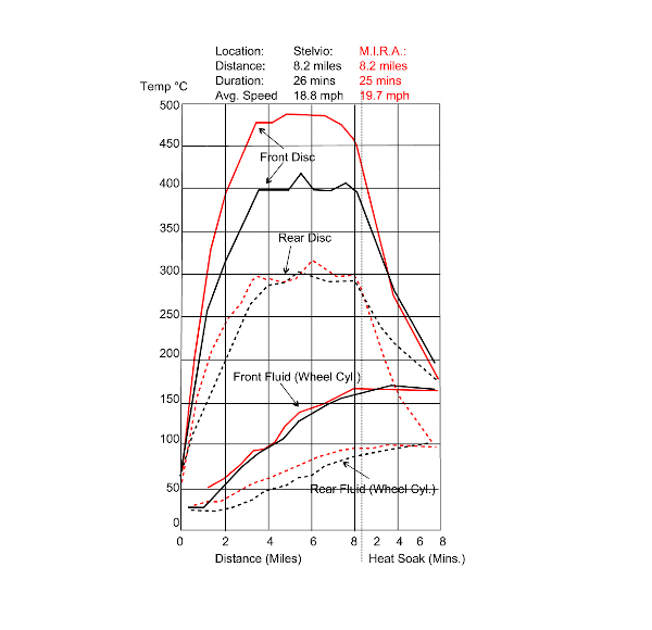
The disc temperatures reached were no higher than those reached on a full fade test but the fluid temperatures were much higher. Some scatter was inevitable but it was found that a trouble-free run was made with fluid temperature reaching 170°C and yet vaporisation was achieved at only 140°C fluid temperature on another run. A different type of shield with an inward flair proved to be a satisfactory modification.
Various schedules have been produced to attempt to reproduce Alpine descents on the level but getting the work, input into the brakes involves stops or pull downs from such high speeds (60 mph) that the cooling conditions are completely upset. It is necessary with such schedules to get front disc temperatures 200°C higher than we recorded in the Alps to raise the fluid temperature to 160°C. A technique which has given reasonable correlation with the Alpine results consists of towing the test vehicle. The towbar is 16 ft long to minimise airflow disturbance round the test car, and is arranged with a pull indicator displayed in the tug vehicle. The tug driver is instructed to maintain the pull decided upon (340 lb. in this case) whilst the test car driver drives as if on the Alps. The speeds are 30 down to 15 mph with 5 checks per minute of about 5 ft/sec2. Three circuits of the inner lane of M.I.R.A. high speed circuit give the right distance. A print of the results of one such run is available for comparison with the Stelvio test.
In testing the effectiveness of methods of petrol exclusion from vacuum systems it has been found that an AC petrol filter with a filter paper on top of the normal wire gauze is a useful trap if the filter is arranged to be on the servo side and the manifold has direct access to the bowl. The trap can be left on the vehicle to collect any petrol let through by the system under test during normal road running, cold starting, throttle blipping or any other useage thought to be causing trouble.
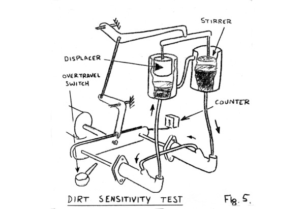
A rig for assessing the dirt sensitivity of different designs of master cylinder is illustrated in the prints. Two master cylinders are operated simultaneously by means of a pneumatic ram at 20-40 strokes a minute. Each is connected in the normal manner. The outputs of the cylinders are linked. The brake fluid used is artificially contaminated with polystyrene filings which have a density similar to brake fluid. The reservoirs are stroked by plungers coupled to the pneumatic ram. One of the plungers is a stirrer but the other is a fluid displacer which causes fluid to be pumped from one reservoir into the other through the communicating pipe. This transfer is arranged to occur during the pressurised phase of the master cylinders so that during recuperation there is a flow as indicated through the master cylinders to carry the foreign matter past the recuperator seals.
An overtravel switch is arranged to stop the test if dirt should prevent the seal from closing which of course results in failure to pressurise and overtravel. The number of strokes to failure recorded by the counter over a number of tests being a measure of the dirt sensitivity or reliability of the particular oylinder type. The same test rig - without the contaminant can be used to measure pressure seal life or bore wear. As well as having to retain hydraulic fluid in the “off” or “on” condition, a master cylinder must refrain from inducing air into the system.
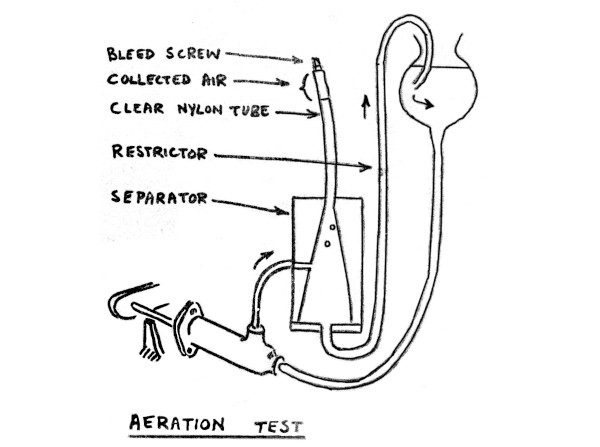
A rig for assessing the aeration standard of a master cylinder is shown in the prints. Air entry is most likely to occur during the release of the piston when a vacuum appears in the master cylinder after the pressure has fallen, but it can continue after the piston has fully returned in two-seal designs where the seals can act as a pump pumping air in the same way as piston rings can pump oil in a worn engine. The test rig strokes the master cylinder as in the dirt sensitivity test but a stroke-stop limiting the stroke to about 7/8 of full master cylinder stroke is necessary since the system is not closed and pressurises dynamically to about 300 lb/in2 due to a restriction in the system.
Any air induced is collected in the clear nylon tube where it can be readily measured. The conical interior of the separator allows air to separate out and rise freely into the collecting tube. Fluid displacement from the master cylinder is returned from the bottom of the separator back to the reservoir. The piping should be as short as possible from the master cylinder to the separator - and rising to avoid trapping air
The most severe testing consists of the long stroke mentioned, as rapid a return as the piston will make under its own return spring and a rest period between return and pressurisation strokes. The rate of stroking will be governed by the choice of rest period found necessary. Examination of air trapping and aeration phenomena can be greatly assisted by the use of perspex models of the parts being studied, but unfortunately brake fluid is inclined to cause obscuration of the perspex by the spread of tiny cracks unless it is coated with a protective lacquer.
Conclusion
In conclusion, I hope that the subject matter has not been too obvious for some or too obscure for others and that the obvious hasn’t been made obscure for any. The aim was rather to clarify the obscure and I hope I’ve had some success.
I would acknowledge the generous help of my friends at Dunlop, Girling and Lockheed whose slides have been an essential part of the lecture and of course, the assistance of my colleagues at the Rover Company.